RAF Ringstead Chain Home Radar Station (AMES12B) 1941 to 1956.

Details
From the A353, turn down to Ringstead and the Beach Cafe. There is a pay car park. Alternatively the turning to Osmington Mills and walk east from the Smugglers INN.

Air battles 1940.

Spitfire reloading.

He111 bombers.
RAF Ringstead Chain Home Radar Station (AMES12B) 1941 to 1956.
Details
RAF Ringstead Chain Home Radar Station (AMES12B) 1941 to 1956.

Google
Details
There are public foot paths that pass all the items connected to the Radar site.
RAF Ringstead was part of the Chain Home (CH) and Chain Home Low (CHL) transmitter/receiver radar. Started in 1940 but too late for the Battle of Britain. It continued service until 1956 by then using the new 'Rotor Radar'. In 1963 part of the site was taken over by the USAF as 2180 Com. Sqn. operating a Tropospheric Scatter System link. This closed down in 1974 and the aerials were removed shortly after.
PB - Pillbox.
SL - Search Light.
CH - Chain Home Radar items.
Sc St - Scatter Station USAAF.
Upton Fort -
Coastal Artillery Battery.
RX - Receiving.
TX - Transmitting
.

Pill box defence against Operation Seelöwe the invasion of Britain.

RX - Tower.

Osmington Mills 1940's.
RAF Ringstead Chain Home Radar Station (AMES12B) 1941 to 1956.

Google
Details
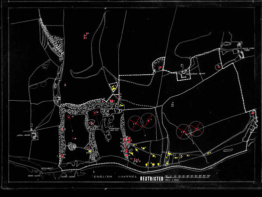
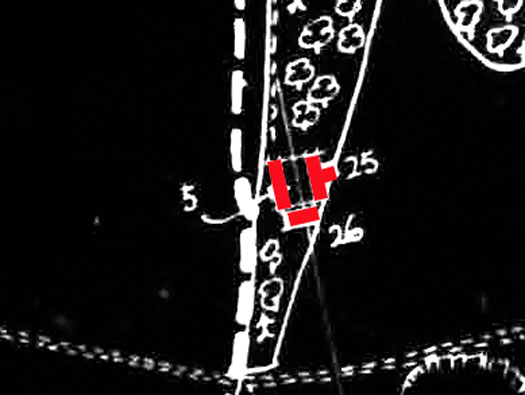
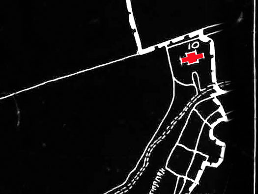
The red squares are where the radar bunkers you can visit, are situated and the four left TX aerials are the Transmitting towers and the two RX to the right are the Receiving towers (now all removed).

TX - Towers.
RX - Tower.

Do17 bombers.
RAF Ringstead Chain Home Radar Station (AMES12B) 1941 to 1956.
Record Site Plan AM 2943/45
Details
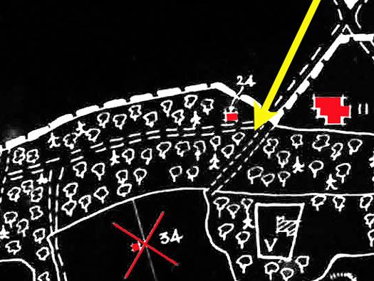
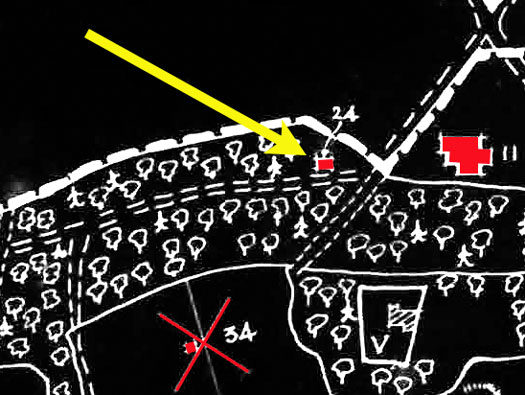
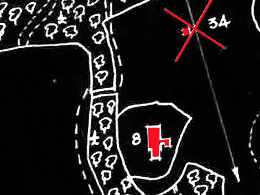
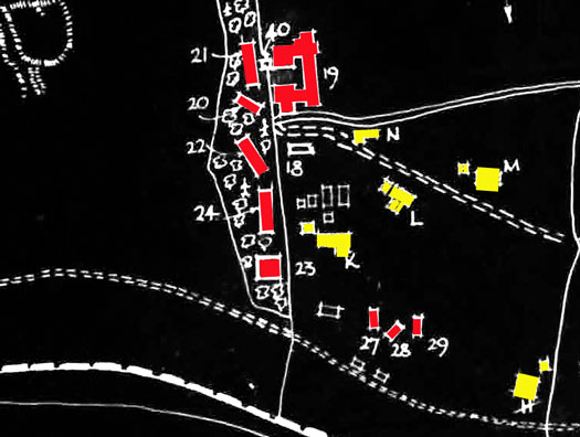
The Air Ministry Site plan of the radar station, covering all but the Communal camp. Red are RAF buildings and Yellow are requestioned private houses.
1 - 'T' 525' Steel Guyed Mast.
2 - 'T' 525' Steel Guyed Mast.
3 - 'T' 525' Steel Guyed Mast.
4 - 'T' 525' Steel Guyed Mast.
5 - 'R' 240' Timber Tower.
6 - 'R' 240' Timber Tower.
7 - 'R' Block - CM - 16087/40.
8 - 'R' Block - CM - 16087/40.
9 - 'T' Block - CM -
16091/40.
10 - 'T' Block - CM - 16091/40.
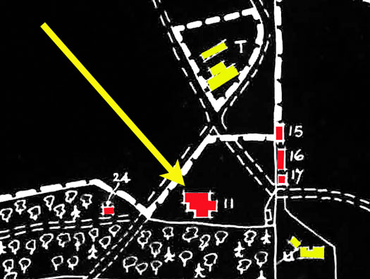
11 - Standby Set House - CM - 5017/41.
12 - Sub Station - CM 1157/40.
13 - 'Q' Building -
Tub&St - 18100/40.
15 -
Air-raid Shelter - C .
16 - First Aid Post - TB - 9058/40.
17 - Watch House - TB - 9061/40.
18 - Orderly Rm - TB -381/41.
19 - Dinning Rm & Institute - TB - 16097/40.
20 - Bath & Ablutions - TB - 12553/40.
21 - Barrack Blk 70' 0" - TB - 9059/40.
22 - Barrack Blk 80' 0" - TB - 9059/40.
23 - Fuel Compound 18'x18'x5'6" - Brick.
24 - Armoury - TB - 606/44/41.
25 - Latrine Blk - TB 5816/42.
26 - 'J' Watch Hut - TB 5816/42.
27 - Defence Hut - N.
28 - Defence Hut - N.
29 - Defence Hut - N.
30 - Defence Hut - N.
31 - Defence Hut - N.
32 - Defence Hut - N.
33 - Comb. 'T'&'R'
Cubicle & 105' Mast - PB - 15046/41.
34 - Comb. 'T'&'R'
Cubicle & 105' Mast - PB - 15046/41.
35 - Defence Hut 36'x16' - N.
36 - Defence Hut 36'x16' - N.
37 - Defence Hut 36'x16' - N.
38 - Gantry - St.
39 - Pump No. Water Supply - Cl-St.
40 - Water Tower 500gal - TB.
TB - Temporary Brick.
PB - Permanent Brick.
C - Concrete.
CM - Concrete Mounded.
N - Nissen Hutting.
St - Steel.
Tub-St - Tubular Steel.
' - feet.
" - inches.
Gal - Gallons.
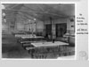
Dinning Rm & Institute - TB - 16097/40.

TB hut.
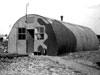
Defence Hut 36'x16' - N, how they may have looked.
RAF Ringstead Chain Home Radar Station (AMES12B) 1941 to 1956.

21 May 2021
Details
To the left is the Emergency Standby Set house bunker.
To the right the route we will take.

Plan.

Two Me109's flying past RAF Swingate aerials 1940.
RAF Ringstead Chain Home Radar Station (AMES12B) 1941 to 1956.

13 October 2003
Details
11 - Standby Set House - CM - 3017/41.
15 -
Air-raid Shelter - C .
16 - First Aid Post - TB - 9058/40.
17 - Watch House - TB - 9061/40.
24 - Armoury - TB - 606/44/41.
Power came from the National Grid, but if the power should be lost, then a very powerful generator
could automatically start up and run the whole system.

Crossley standby set 'West Coast Type'.

National Grid.
RAF Ringstead Chain Home Radar Station (AMES12B) 1941 to 1956.

05 February 2012
Details
11 - Standby Set House - CM - 3017/41.
Standby set house entrance.

Erk at work.
RAF Ringstead Chain Home Radar Station (AMES12B) 1941 to 1956.

Scarlett Point
Details
11 - Standby Set House - CM - 3017/41.
Two entrances, one for machinery and the other for personnel.

Generator.

AIR 16-939
RAF Ringstead Chain Home Radar Station (AMES12B) 1941 to 1956.

Upton Plant Architects
Details
11 - Standby Set House - CM - 3017/41.
Standby set house personnel entrance.
Planning permission has been applied for to turn it into a holiday home, actually a very good idea, as it will preserve it.

They may have been issued with for bicycles.
RAF Ringstead Chain Home Radar Station (AMES12B) 1941 to 1956.

Upton Plant Architects
Details
11 - Standby Set House - CM - 3017/41.
Standby set house
RAF Ringstead Chain Home Radar Station (AMES12B) 1941 to 1956.

Air 16/939 RDF Ground Stations
Details
11 - Standby Set House - CM - 3017/41.
Power Plant standby set house as it may have looked.
RAF Ringstead Chain Home Radar Station (AMES12B) 1941 to 1956.

Air 10/4152 Ground Stations RAF
Details
11 - Standby Set House - CM - 3017/41.
Standby set house
Huge engines with large generators that were needed to energize the radar systems.
RAF Ringstead Chain Home Radar Station (AMES12B) 1941 to 1956.

15 November 2017
Details
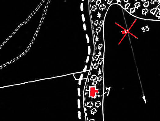
From, 33 - Comb. 'T' D-'R' Cubicle & 105' Mast - PB - 15046/41.
Aerial tie down
This is the ex RAF roadway, on the left is a chunk of concrete, part of a cable tie down probably for an aerial.

Aerial & tie down.
RAF Ringstead Chain Home Radar Station (AMES12B) 1941 to 1956.

15 November 2017
Details
Part of the 33 - Comb. 'T' D-'R' Cubicle & 105' Mast - PB - 15046/41.
Aerial tie down

Red - early Chain Home coverage.
Yellow - later
Chain Home coverage.

4 x TX - Transmit aerials steel.
The way Chain Home worked was very like turning a flood light on and pointing it outwards away from where you wish to defend. This (flood light) was four steel framed aerials. Laid out in a straight line pointing towards your enemy. When an aircraft flew into the (flood light), the reflection is bounced off the plane and returned to (east coast four, west coast two, aerials) here two large wooden aerials.

2 x RX - Receiver aerials wooden.
The bounced reflection is received in the two RX bunkers and when seen by the operators, a message would be sent to a filter station. They would work out the threat and then send up fighters to intercept the bombers.
This is a simple description and I hope it helps, there are many websites that explain it better than I can.
RAF Ringstead Chain Home Radar Station (AMES12B) 1941 to 1956.

15 November 2017
Details
From, 33 - Comb. 'T' D-'R' Cubicle & 105' Mast - PB - 15046/41.
Steel hook to support an aerial.
TX Towers.

Looking up an RX aerial.
RAF Ringstead Chain Home Radar Station (AMES12B) 1941 to 1956.

15 November 2017
Details
24 - Armoury - TB - 606/44/41.
I have wondered what this hut was for and the only answer I have is, that it was the radar sites guard room.

Guard room.

John O'Neil was stationed here in the 1950's when he was doing his National Service. The picture is the Ringstead Cricket team, all members of the Chain Home Radar crew.
RAF Ringstead Chain Home Radar Station (AMES12B) 1941 to 1956.

13 October 2003
Details
24 - Armoury - TB - 606/44/41.
A standard RAF temporary brick building guard room.
RAF Ringstead Chain Home Radar Station (AMES12B) 1941 to 1956.

13 October 2003
Details
24 - Armoury - TB - 606/44/41.
The original paint on the door. In fact the door is still in very good condition.

RAF Police.
They may have used Police dogs to patrol the site.
RAF Ringstead Chain Home Radar Station (AMES12B) 1941 to 1956.

13 October 2003
Details
24 - Armoury - TB - 606/44/41.
RAF Ringstead Chain Home Radar Station (AMES12B) 1941 to 1956.

13 October 2003
Details
24 - Armoury - TB - 606/44/41.
Looking inside.
RAF Ringstead Chain Home Radar Station (AMES12B) 1941 to 1956.

Hut plan.
Details
24 - Armoury - TB - 606/44/41.
Plan of the building. A wartime temporary brick hut design.

Temporary Brick bonding. The brick pointing at 90° from the wall, took the roof support beam.
RAF Ringstead Chain Home Radar Station (AMES12B) 1941 to 1956.

13 October 2003
Details
The RAF road
Continuing along the roadway.

They would have had their own three ton lorry as transport.

An RAF Jeep which they also may have been issued.

The Austin Utility is another vehicle that may have been used.
RAF Ringstead Chain Home Radar Station (AMES12B) 1941 to 1956.

13 October 2003
Details
Continuing along the roadway.
X is the way to the first RX bunker.

Plan.
RAF Ringstead Chain Home Radar Station (AMES12B) 1941 to 1956.

13 October 2003
Details
8 - 'R' Block - CM - 16087/40.
First receiver bunker.
'C' Type Receiver Block (West Coast Type)

Plan.
RAF Ringstead Chain Home Radar Station (AMES12B) 1941 to 1956.

12 February 2012
Details
8 - 'R' Block - CM - 16087/40.
'C' Type Receiver Block (West Coast Type)
Crew entrance.
Members of the radar crew.
RAF Ringstead Chain Home Radar Station (AMES12B) 1941 to 1956.

12 February 2012
Details
8 - 'R' Block - CM - 16087/40.
'C' Type Receiver Block (West Coast Type)
Blast wall crew entrance.

Entrance plan.

Plan.
RAF Ringstead Chain Home Radar Station (AMES12B) 1941 to 1956.

12 February 2012
Details
8 - 'R' Block - CM - 16087/40.
'C' Type Receiver Block (West Coast Type)
N - Personnel Entrance.
Plan.
RAF Ringstead Chain Home Radar Station (AMES12B) 1941 to 1956.

12 February 2012
Details
8 - 'R' Block - CM - 16087/40.
'C' Type Receiver Block (West Coast Type)
N - Personnel Entrance.
Plan.
RAF Ringstead Chain Home Radar Station (AMES12B) 1941 to 1956.

Scarlett Point
Details
'C' Type Receiver Block (West Coast Type)
A - Goods Entrance.
B - Earth Bank.
C - Transformer Room.
D - Switch Gear.
E - Pump.
F - Filter Unit.
G - Roof Vent.
H - Electric Part Store.
I - Receiver Equipment.
J - Electro-mechanical Calculator.
K - L - Cable Ducts.
M - Battery Room GPO.
N - Personnel Entrance.
RAF Ringstead Chain Home Radar Station (AMES12B) 1941 to 1956.

12 February 2012
Details
8 - 'R' Block - CM - 16087/40.
'C' Type Receiver Block (West Coast Type)
M - Battery Room GPO. The GPO (General Post Office) ran all the phone lines around the country, so all the CH radars would have had cables laid and connected to the main telephone network.

A telephone of the day.

Post Office van 1940's.
RAF Ringstead Chain Home Radar Station (AMES12B) 1941 to 1956.

12 February 2012
Details
8 - 'R' Block - CM - 16087/40.
'C' Type Receiver Block (West Coast Type)
H - Electric Part Store.

Plan.
RAF Ringstead Chain Home Radar Station (AMES12B) 1941 to 1956.

12 February 2012
Details
8 - 'R' Block - CM - 16087/40.
'C' Type Receiver Block (West Coast Type)
L - Cable Ducts.

Plan.
RAF Ringstead Chain Home Radar Station (AMES12B) 1941 to 1956.

12 February 2012
Details
8 - 'R' Block - CM - 16087/40.
'C' Type Receiver Block (West Coast Type)
I - Receiver Equipment.

Plan.
RAF Ringstead Chain Home Radar Station (AMES12B) 1941 to 1956.

Air 10/4152
Details
Chain Home receiver room photograph shows console (right) and RF8N Receiver (left).
Plan.
RAF Ringstead Chain Home Radar Station (AMES12B) 1941 to 1956.

12 February 2012
Details
8 - 'R' Block - CM - 16087/40.
'C' Type Receiver Block (West Coast Type)
K - L - Cable Ducts.
RAF Ringstead Chain Home Radar Station (AMES12B) 1941 to 1956.

12 February 2012
Details
8 - 'R' Block - CM - 16087/40.
'C' Type Receiver Block (West Coast Type)
J - Electro-mechanical Calculator.
RAF Ringstead Chain Home Radar Station (AMES12B) 1941 to 1956.

Air 10/4152
Details
'C' Type Receiver Block (West Coast Type)
J - Electro-mechanical Calculator.
RAF Ringstead Chain Home Radar Station (AMES12B) 1941 to 1956.

12 November 2012
Details
8 - 'R' Block - CM - 16087/40.
'C' Type Receiver Block (West Coast Type)
Gas filtration plant room.
D - Switch Gear.
E - Pump.
F - Filter Unit.
G - Roof Vent.

Gas filtration plant room.

A broken roof vent on the roof of the TX block.
RAF Ringstead Chain Home Radar Station (AMES12B) 1941 to 1956.

Air 10/4152
Details
'C' Type Receiver Block (West Coast Type)
Gas filtration plant room.
D - Switch Gear.
E - Pump.
F - Filter Unit.
G - Roof Vent.
Gas filtration plant room.
RAF Ringstead Chain Home Radar Station (AMES12B) 1941 to 1956.

12 February 2012
Details
8 - 'R' Block - CM - 16087/40.
'C' Type Receiver Block (West Coast Type)
I - Receiver Equipment.
Plan.
RAF Ringstead Chain Home Radar Station (AMES12B) 1941 to 1956.


12 February 2012
Details
8 - 'R' Block - CM - 16087/40.
'C' Type Receiver Block (West Coast Type)
A - Goods Entrance.
C - Transformer Room.

Plan.

Transformers in an M & E plinth on an RAF airfield somewhere in England, gives an idea of what would be there.
RAF Ringstead Chain Home Radar Station (AMES12B) 1941 to 1956.

08November 2012
Details
Nissen Hut
There must have been a few around here. I have found several bases of huts here.

16ft Nissen hut.
RAF Ringstead Chain Home Radar Station (AMES12B) 1941 to 1956.


12 February 2012
Details
Nissen hut.
There are no details on the site plan of these huts?
RAF Ringstead Chain Home Radar Station (AMES12B) 1941 to 1956.

12 February 2012
Details
More hut remains.
-100.jpg)
Building a Nissen hut.
RAF Ringstead Chain Home Radar Station (AMES12B) 1941 to 1956.

12 February 2012
Details
Either a cable bridge or a pathway, I think it was a bridge to carry very heavy cables across the stream from the aerials to the bunkers.

Plan.
RAF Ringstead Chain Home Radar Station (AMES12B) 1941 to 1956.

AIR 16/939
Details
Cabling from the aerials.
RAF Ringstead Chain Home Radar Station (AMES12B) 1941 to 1956.

12 February 2012
Details
At the end of the path you reach the sea. I have seen in the past, with barbed wire and picket posts set between the beach and the coast path, these have all been cleaned away.

Barbed wire.

Screw picket posts.
RAF Ringstead Chain Home Radar Station (AMES12B) 1941 to 1956.

20 May 2021
Details
Walking west along the coast path and there
is a style on the right side and a path crossing this track leading into the next wood.
RAF Ringstead Chain Home Radar Station (AMES12B) 1941 to 1956.

12 February 2012
Details
We have just been walking through the far wood and down to the sea, now walking west along the coast path, there is a style on the right and you cross this track between two fields. And then enter the next wood that runs north.
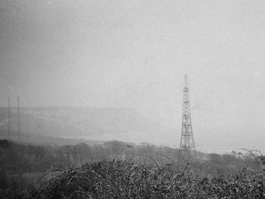
The field we can see in this picture shows NO signs of what it once held. There were twin parabolic aerials of the US Airforce Tropospheric Scatter radio-relay link to Spain. The system at Ringstead was operated by the USAF No. 6 Detachment, 2180 Communications Squadron from Dec 1963 to 1974, with the two massive aerial arrays dismantled by March 1975. Ronald Searle, Geograph.

Plan.
RAF Ringstead Chain Home Radar Station (AMES12B) 1941 to 1956.

USAF Scatter Station
Details
US Airforce Tropospheric Scatter radio-relay link to Spain, they were huge ,150ft high. As children I remember coming to Ringstead at the time these were here, although I remember the four steel masts or remains of them, I do not ever remember seeing these. It was closed by 1970 and dismantled in 1974.

 2180 Com. Sqn. USAF.
Microwave radio messages could be sent over long distances by using the Troposphere as a sounding board and bouncing the signals back to the next station.
RAF Ringstead Chain Home Radar Station (AMES12B) 1941 to 1956.

0153 1972 Dorset CC
Details
US Airforce Tropospheric Scatter radio-relay link from a 1972 air photo.
RAF Ringstead Chain Home Radar Station (AMES12B) 1941 to 1956.

USAF Scatter Station
Details
US Airforce Tropospheric Scatter radio-relay link being dismantled.

A crawler crane like the one that was used here. I was told they brought a crane on a lorry all the way down and along the track/roadway to the Scatter station, to remove it. Everything was removed.
RAF Ringstead Chain Home Radar Station (AMES12B) 1941 to 1956.

20 May 2021
Details
5 - 'R' 240' Timber Tower - Mast.
One of the RX - Receiver wooden aerials concrete base.
There are four bases if you can find them in the woodland.
RX - Receiver wooden aerials.
RX - Receiver wooden aerials.
RAF Ringstead Chain Home Radar Station (AMES12B) 1941 to 1956.

20 May 2021 ------------------------------------------------------------------- John O'Neill
Details
5 - 'R' 240' Timber Tower - Mast.
25 - Latrine Blk. - TB - 5816/42.
26 -
'J' Watch Hut - TB - 5816/42.
One of the RX - Receiver wooden aerials concrete base.
The path looking south, there are four all together. Hard to find in summer, so head out in winter and they should show up.
This is how the wooden tower wood have looked, this is the eastern on, I do not have a picture of the western on.
RAF Ringstead Chain Home Radar Station (AMES12B) 1941 to 1956.

20 May 2021
Details
7 - 'R' Block - CM - 16087/40.
'C' Type Receiver Block.
Crew entrance.
RAF Ringstead Chain Home Radar Station (AMES12B) 1941 to 1956.

12 February 2012
Details
7 - 'R' Block - CM - 16087/40.
'C' Type Receiver Block
A - Goods entrance.
RAF Ringstead Chain Home Radar Station (AMES12B) 1941 to 1956.
Scarlett Point
Details
'C' Type Receiver Block plan
A - Goods Entrance.
B - Earth Bank.
C - Transformer Room.
D - Switch Gear.
E - Pump.
F - Filter Unit.
G - Roof Vent.
H - Electric Part Store.
I - Receiver Equipment.
J - Electro-mechanical Calculator.
K - L - Cable Ducts.
M - Battery Room GPO.
N - Personnel Entrance.
RAF Ringstead Chain Home Radar Station (AMES12B) 1941 to 1956.

20 May 2021
Details
7 - 'R' Block - CM - 16087/40.
'C' Type Receiver Block
C - Transformer Room.
RAF Ringstead Chain Home Radar Station (AMES12B) 1941 to 1956.

20 May 2021
Details
7 - 'R' Block - CM - 16087/40.
'C' Type Receiver Block
A - Goods entrance.
RAF Ringstead Chain Home Radar Station (AMES12B) 1941 to 1956.

12 February 2012
Details
7 - 'R' Block - CM - 16087/40.
'C' Type Receiver Block
All the insides of the 'C' type blocks would have looked exactly alike. The reason that there are two, if one had been hit by a bomb, the other one could take over and continue working.
RAF Ringstead Chain Home Radar Station (AMES12B) 1941 to 1956.

12 February 2012
Details
7 - 'R' Block - CM - 16087/40.
'C' Type Receiver Block
Gas filtration plant room.
D - Switch Gear.
E - Pump.
F - Filter Unit.
G - Roof Vent
RAF Ringstead Chain Home Radar Station (AMES12B) 1941 to 1956.

12 February 2012
Details
7 - 'R' Block - CM - 16087/40.
'C' Type Receiver Block
J - Electro-mechanical Calculator.
RAF Ringstead Chain Home Radar Station (AMES12B) 1941 to 1956.

12 February 2012
Details
7 - 'R' Block - CM - 16087/40.
'C' Type Receiver Block
I - Receiver Equipment.
RAF Ringstead Chain Home Radar Station (AMES12B) 1941 to 1956.

12 February 2012
Details
7 - 'R' Block - CM - 16087/40.
'C' Type Receiver Block
L - Cable Ducts.
RAF Ringstead Chain Home Radar Station (AMES12B) 1941 to 1956.

12 February 2012
Details
7 - 'R' Block - CM - 16087/40.
'C' Type Receiver Block
A - Goods Entrance.
RAF Ringstead Chain Home Radar Station (AMES12B) 1941 to 1956.

12 February 2012
Details
More Nissen hut bases.

Nissen hut.
RAF Ringstead Chain Home Radar Station (AMES12B) 1941 to 1956.

12 February 2012
Details
The path continues back to the road. Its a lovely walk.
RAF Ringstead Chain Home Radar Station (AMES12B) 1941 to 1956.

12 February 2012
Details
The military road and bridge.
RAF Ringstead Chain Home Radar Station (AMES12B) 1941 to 1956.

12 February 2012
Details
Sunset through the woods.
RAF Ringstead Chain Home Radar Station (AMES12B) 1941 to 1956.

20 May 2021
Details
Transmitter Block. There were main and reserve blocks. 9 - 'T' Block - CM 16091/40 & 12 - Sub - Station - CM - 1137/41up on the hill around the farms. I have never found this one yet.
18 - Orderly Rm - TB -381/41.
19 - Dinning Rm & Institute - TB - 16097/40.20 - Bath & Ablutions - TB - 12553/40.
21 - Barrack Blk 70' 0" - TB - 9059/40.
22 - Barrack Blk 80' 0" - TB - 9059/40.
23 - Fuel Compound 18'x18'x5'6" - Brick.
24 - Armoury - TB - 606/44/41.
27 - Defence Hut - N.
28 - Defence Hut - N.
29 - Defence Hut - N.
The letters H,K,L,M & N are some of the requestioned houses.

Plan.
RAF Ringstead Chain Home Radar Station (AMES12B) 1941 to 1956.

20 May 2021
Details
Continuing on an easterly course along the sea front and the slight left and start climbing.

Plan.
RAF Ringstead Chain Home Radar Station (AMES12B) 1941 to 1956.

20 May 2021
Details
10 'T' Block - CM - 16091/40.
TX Block, continue along the track and a gate on the left allows you to get into the field to see it.
RAF Ringstead Chain Home Radar Station (AMES12B) 1941 to 1956.

20 May 2021
Details
10 'T' Block - CM - 16091/40.
TX Block.
View through the trees.

Plan.
RAF Ringstead Chain Home Radar Station (AMES12B) 1941 to 1956.

Scarlett Point
Details
Second TX Block. Plan.
A - Roof vent.
B - Bay for cable feed troughs.
C - Cable ducts 80cm deep.
D - Transmitter equipment.
E - Goods entrance.
F - Personnel entrance.
G - Transformer room.
H - Ventilation system.
RAF Ringstead Chain Home Radar Station (AMES12B) 1941 to 1956.

20 May 2021
Details
10 'T' Block - CM - 16091/40.
TX Block.
The entrance and on the right the cable entrances.
Plan.
RAF Ringstead Chain Home Radar Station (AMES12B) 1941 to 1956.

NT
Details
10 'T' Block - CM - 16091/40.
TX Block.
Nice description of the radar.
Radar coverage.
RAF Ringstead Chain Home Radar Station (AMES12B) 1941 to 1956.

Scarlet Point
Details
Scarlet Point's TX Block.
Note the air vents and chimneys for the air conditioning and anti gas systems.
RAF Ringstead Chain Home Radar Station (AMES12B) 1941 to 1956.

20 May 2021
Details
10 'T' Block - CM - 16091/40.
TX Block.
.TX cables would have come out of here and out to the aerials.
B - Bay for cable feeds.
RAF Ringstead Chain Home Radar Station (AMES12B) 1941 to 1956.
20 May 2021
Details
Cabling.
RAF Ringstead Chain Home Radar Station (AMES12B) 1941 to 1956.

20 May 2021
Details
10 'T' Block - CM - 16091/40.
TX Block.
Crew entrance.
RAF Ringstead Chain Home Radar Station (AMES12B) 1941 to 1956.

12 February 2012
Details
10 'T' Block - CM - 16091/40.
TX Block.
The view inside from the machinery entrance.
RAF Ringstead Chain Home Radar Station (AMES12B) 1941 to 1956.

AIR 16-939
Details
10 'T' Block - CM - 16091/40.
West Coast CH Type Transmitter Room.

T3026 Transmitter Control Desk.
RAF Ringstead Chain Home Radar Station (AMES12B) 1941 to 1956.

AIR 16-939
Details
West Coast Transmitter 'T' 3104.
RAF Ringstead Chain Home Radar Station (AMES12B) 1941 to 1956.

12 February 2012
Details
10 'T' Block - CM - 16091/40.
TX Block.
A - Roof vents.
********************************************************************DO NOT TOUCH ANYTHING BELOW HERE!!!*********************************************************************-->
 Norway (coming soon!)
 France
 Great Britain


